Monday, October 29, 2012

0 Arduino Robot 1 - The InsectBot

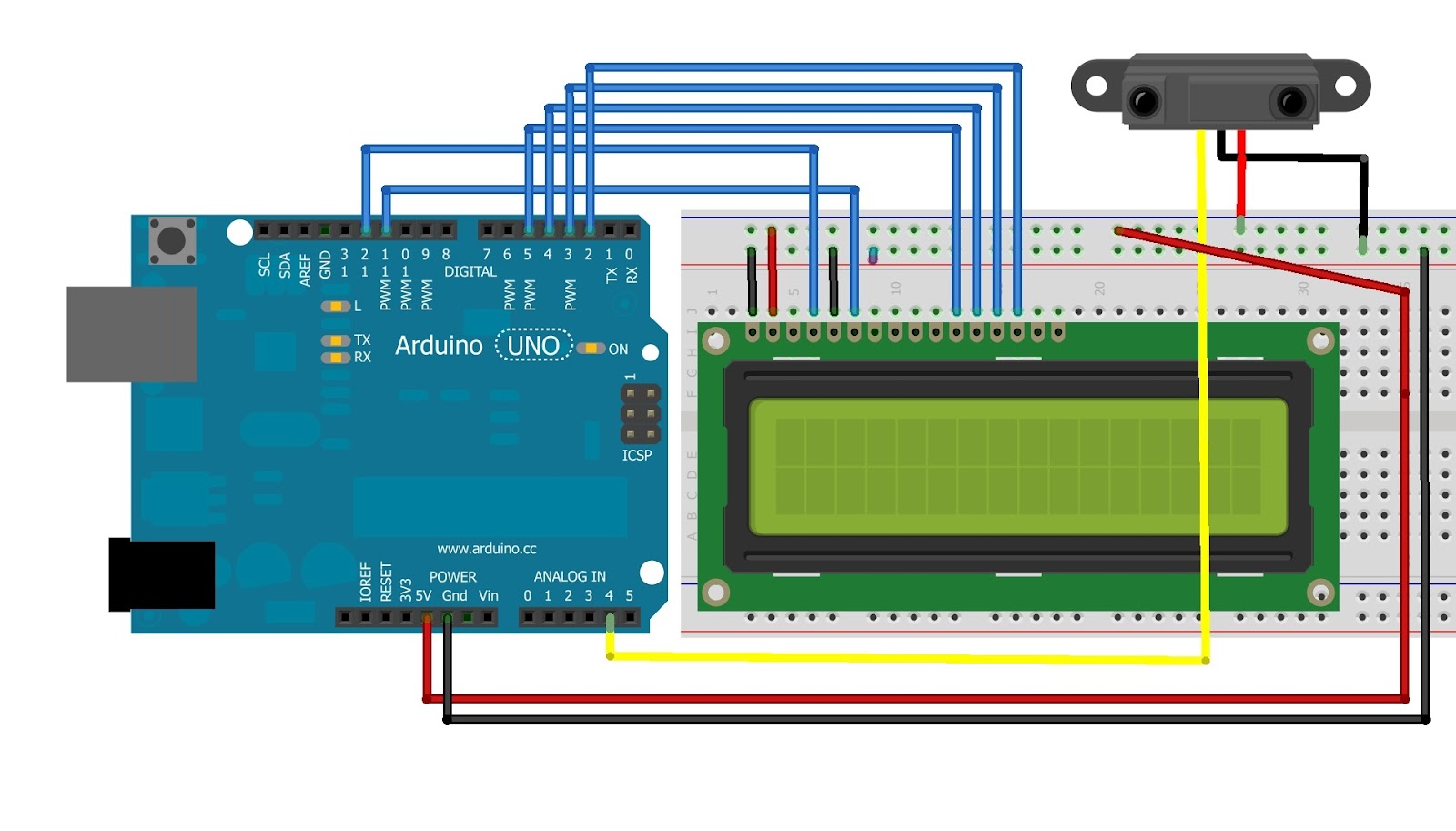
Hi, guys! I hope you liked my earlier post on making a distance display. So here I am again, and this time I'm going to show you, how to build a robot! Though it's not much of a robot, but I'm sure it'll be fun to watch! Basically the Insect will just squirm it's way around, but if you want, you can actually connect a distance sensor to the arduino and use it for object detection and avoidance!
So let's get started! 

You're gonna need :

  • Arduino Board
  • 2 Servo Motors (I prefer micro servos)
  • Stiff wire ( I used an old hanger wire)
  • 9v battery and it's clip
  • Heat Shrink tubing
  • Glue
  • My tutorial on controlling Servos
So first you need to bend the wire to make it look something like the pic below. Basically this is the structure of the legs.

Then you need to glue the wires to the attachment for the Servo. And it should look something like this.

After that, you need to attach the servos together to make it look like this. These will be the main body of the Insect.

Put in the code for centering the Servos. Then attach the legs to them. You've just created the body for your very first robot! Now attach the servos to the Arduino Board as I showed in  my tutorial, and then program the Insect for the walk. The Code is given below:

//For Centering the servo


Servo fServo;
Servo rServo; 
void setup()
{
fServo.attach(8);
rServo.attach(9); 
fServo.write(90); 
rServo.write(90);
}
void loop()
{
delay(500);
}

//For the Walk


#include <Servo.h>
Servo fServo;
Servo rServo;
int center = 90; 
int frUp = 72; 
int flUp = 108; 
int brForward = 75; 
int blForward = 105;
void moveForward()
{
frontServo.write(frontRightUp);


rServo.write(blForward);
delay(125);
fServo.write(center);
rServo.write(center);
delay(65);
fServo.write(flUp);
rServo.write(brForward);
delay(125);
fServo.write(center);
rServo.write(center);
delay(65);
}
void setup()
{
fServo.attach(8);
rServo.attach(9);
}
void loop()
{
moveForward(); 
delay(150); //time between each step taken, speed of walk
}

Now all you have to do is just plug out the Arduino from the USB, plug in a battery and make the Board a rider on the insect!
Although this was just like a 'Hello World' Project for Robotics, I'll be posting many more progressively projects on Robotics! So don't forget to check in every now and then!
Cheers!


Sunday, October 28, 2012

0 Got the new Raspberry Pi?! A Guide to setting it up!

 
I'm sure most of the people reading this must've heard of the Raspberry Pi. No? What?! Have you been living on Mars?! So even if you've not heard of it, I'm gonna tell you all about it in this post.

The Raspberry Pi is basically a credit card sized computer that was developed with the intention of helping students learn programming and developing their own applications with them. Well, I must say, it has succeeded phenomenally in that respect. The board has a Broadcom BCM2835 SoC design, which includes an ARM1176JZF-S 700 MHz processor, VideoCore IV GPU, a RAM of 256MB (later upgraded to 512MB). It has no hard drive but uses an SD card for storage. The Raspberry Pi foundation currently provides a Debian linux based operating system called the Wheezy Raspbian. There are tools planned for supporting python as the main programming language.
The Raspberry Pi, is a very powerful package with which you can have fun and learn at the same time! It can also play full 1080p movies!

Here is a Voice Controlled Robotic Arm built using the Raspberry Pi .


 You can order your Raspberry Pi from element14.com.
The potential applications for this great computer are indefinite. Some of these are

  • Home Automation
  • Robotics
  • Media Streaming
  • Gaming Arcade
  • etc!
So you got your Raspberry Pi and you know that it is some kind of a computer, but how to set it up?! The basic things you need are

  • A keyboard 
  • A mouse
  • A microUSB charger (any android charger will do)
  • An HDMI cable (To use a monitor)
  • An Ethernet Cable for internet access
  • An SD card for storing the boot image

Install the Boot image on the SD card

Now, I'm assuming you all have windows installed on your computer.
The software I'm going to use is the Win32DiskImager, which can be downloaded from here once you've done that, you can download the Raspbian OS image from here. Unzip both of them(preferably in the same directory). Insert the SD card into your reader, and then fire up the Win32DiskImager from the binary folder. As soon as the program is executed you will see an error. Ignore that. Now select the Raspbian image by clicking the blue folder icon and navigating to the folder you unzipped. Then select your SD card from the devices and click Write, and lean back sip some coffee while your linux is loaded. When the progress is complete, take out the SD card. Behold the card! For it holds the key to unlocking a pandoras box full of inventions! No plug in your sd card into the Raspberry Pi and power it up! You'll be greeted by a something called a 'raspi-config'. Nothing too fancy, just a configuration tool, where you need to change some options.

First up, select expand_rootfs, then ok. What this does is adjust your partition to utilize your card space fully. You don't want that extra space left out now do you?

Next, enable the Overscan. It adjusts the screen size of the linux to use all of your monitor real estate. If however, your screen is already full then don't care about this.

Now comes the most important part, setting up your keyboard. Press enter on the configure_keyboard option and just press enter again! The 105-key option is good for you. Then select other if you keyboard is different that a UK layout. After that select the English(US) option. Select default on the next and 'no compose key' after that. The last option is to set ALT/CTRL/BACKSPACE to kill the GUI. This would help if the linux crashed and you want to put it back up without rebooting.

You can keep a new UNIX password by going to change_pass and typing in a new password. 

Then you need to set your locale. Just deselect the en_GB option and select the option in which the two letters match your country's. Then select the region and the timezone and that's it! You're done!

On the main menu, select finish and reboot! Now take a moment and look at what you have done! You've just opened a pandora's box full of new opportunities in learning and having fun!

After the system reboots, type in pi as your login and then the password you set earlier. Then type in startx to start the GUI session. And there it is! The LXDE window manager. Now you can treat it like a normal computer! Watch movies, play games, surf the web.

But of course, if you want to develop something using it, then Python is your best friend! You can fire up the IDLE 3 kept on the desktop and use it to develop apps for your Pi. For tutorials on Python Programming Language, head out to the official Python website. You can also buy a GertBoard, to go to increase you GPIO pins, so that you can connect more sensors and peripherals to it. And for those interested in Robotics, just imagine what all you can do with so powerful a processor!! Oh wait, you can also interface to board with Arduino!!

Personally, I would love to load the BackTrack Linux on it and be hacking everyone! 
Here's a list of all the Operating systems that this Board Supports-


  • AROS
  • Android 4.0 (Ice Cream Sandwich)
  • Arch Linux ARM
  • Debian Squeeze
  • FreeBSD
  • Firefox OS
  • Gentoo Linux
  • Google Chrome OS
  • NetBSD
  • Raspberry Pi Fedora Remix
  • Open webOS
  • Raspbian (Debian Wheezy port with faster floating point support)
  • RISC OS
  • Slackware ARM (formerly ARMedslack)
  • QtonPi a cross-platform application framework based Linux distribution based on the Qt framework
I'll be putting up tutorials on using the Pi, from time to time. So keep checking! 
You can also subscribe to this site by using the RSS feed at the top of the page. Interact with the social widget on the right! 
Cheers!!


Friday, September 28, 2012

0 Arduino Project 7 - Connect an LCD module to an Arduino and Make a distance display.

You are starting to build confidence in your arduinoing capabilities now aren't you? Gives you satisfaction to know that you are really progressing in something doesn't it? Right! So that's why I'm here with a new tutorial which will show you how to interface an LCD with your arduino. Although it involves some amount of soldering and wiring, it's still a fairly easy concept to grasp. Once you get the theory behind how an LCD module is connected, you will have no difficulty in remembering how to connect it the next time you want to use it. So let's get started shall we?
In this tutorial, we will use a 16X2 LCD having HD44780 driver. You can identify them by their 16 pin connectors.
Okay so first off, I'm going to list out the function of each pin of the LCD module.
Each LCD has 16 pins of which we will be using 12 today.

VCC - Ground Voltage
VDD - +5V
RS    - Register Select controls where in the LCD's memory the data is being written.
R/W  - Read/Write, enables reading or writing mode
E       - Enables writing to the registors
D0-8 - Data Transfer buses
Vo    - Controls the Contrast
A and K control the LED backlight.

Wiring the LCD to the Arduino Via a Breadboard

Wire up the circuit according to the figure given below (courtesy : www.arduino.cc ).

Software for Reading and Writing Data from and to the LCD

The following code will allow you to enable the serial function of the arduino to communicate with it and consequently to give instructions to it to control the LCD module.

#include <LiquidCrystal.h>
// LiquidCrystal display with:
// rs on pin 12
// rw on pin 11
// enable on pin 10
// d4-7 on pins 5-2
LiquidCrystal lcd(12, 11, 10, 5, 4, 3, 2);
void setup()
 {
 Serial.begin(9600);
 lcd.begin(16, 2);
 lcd.clear();
 lcd.setCursor(0,0);
 lcd.print("It Works!");
 lcd.setCursor(0,1);
 lcd.print("Rules");
 }
void loop()
 {
   if (Serial.available())
   {
       char ch = Serial.read();
       if (ch == '#')
        {
            lcd.clear();
         }
       else if (ch == '/')
         {
             lcd.setCursor(0,1);
          }
       else
  {
     lcd.write(ch);
   }
 }
}

Now upload the code to the board, open the Serial Monitor from the console and enter some text to try it out!


Next I will use an IR ranger sensor to measure the distance of an object and print the values to the LCD. This is a little more complex code and function, so I suggest that before reading this tutorial, you read my tutorial on working with IR sensors.  
Okay, now hook up the LCD module according to the instructions above but add the IR sensor on the analog pin 4 so that the whole circuit looks like this:

Now this is the code for the assembled hardware.

#include <LiquidCrystal.h>
// LiquidCrystal display with:
// rs on pin 12
// rw on pin 11
// enable on pin 10
// d4-7 on pins 5-2
LiquidCrystal lcd(12, 11, 10, 5, 4, 3, 2);
int irPin = 4;
void setup()
 {
 lcd.begin(16, 2);
 lcd.clear();
 pinMode(irPin, INPUT);
 }

void loop()
 {
  float volt = analogRead(irPin)*0.0048828125;   
  float val = 65*pow(volt, -1.10);         
  lcd.print(val);                     
  delay(100);
}

The code in loop is the program is for the displaying the actual distance of the obstacle, rather than the analog values of the Sharp IR sensor. To get an explanation for how it works, you can go to this link. (I'm too lazy to explain the whole process!) or if you do not want to get the distance, only the analog values then you can replace this:

 float volt = analogRead(irPin)*0.0048828125;   
  float val = 65*pow(volt, -1.10);         
  lcd.print(val);                     
  delay(100);

by this:

val = analogRead(irPin);
lcd.print(val);
delay(100);
Like this project, you can build others like a digital thermometer! Or for that matter any project that involves analog values. Don't take any guidance on that, first try it yourself.
Have fun with your new project and needless to say, whenever in doubt just comment on the post, mail me or google it!!

Cheers! :)


Friday, September 21, 2012

0 The MakerBot Replicator 2 - The Best in 3D Printing

So here's a new addition to my wishlist! The replicator 2! It's bigger, faster, more efficient and sturdier than the original replicator. Plus it's "Hand-assembled in Brooklyn, NY". It's now considered the best 3D printer in existence and has set a benchmark for future ones. But in addition to the upgrades which make it a fantastic machine, there is an increase in price which make it a deal breaker for many buyers. According to the CEO of MakerBot, the Replicator was designed with the serious designers in mind, not the tinkerers. So let's see what all has the Replicator to offer.

A mere look at the Replicator 2 tell us that it can do some serious stuff. Of course! The body is now made of  powder-coated steel with PVC which themselves give an aura of profesionalism around the printer. In addition to better look and feel, MakerBot has added a new plastic called PLA based on corn which doesn't expand on heating, so doesn't contract on cooling. This results in less cracking and better models! Another really good advancement is the increase in resolution. Earlier, the Replicator used to print in layers of 270microns, but the Replicator 2 does that in layers of only 100 microns. It means that the layers of plastic are paper thin.
Another good thing is that it comes fully assembled and you only need to plug the power in to get started. The biggest complaint that has been addressed is the levelling system. The upgraded version has a three point system rather than a four point one carried by the original model, and is much easier to use. It also has a 37% increase in the printing volume.


To run the beast, there's a new CAD software called the MakerWare, which is easily one of the better CAD tools. You can drag, drop components on a virtual building platform and also tweak them, either independently or simultaneously.
You would you like to get a slice of 3D printing? Thought so! You can just go out and order the printer online! Except that it costs $2,199 and has a 3 month waiting period which can be even more if you want to get it shipped from the states to any other country.


Share with me your reviews on the report and follow me on twitter.
Cheers!

Tuesday, September 18, 2012

0 Arduino Project 6 - Inputting Analog Values into Arduino and mapping them to control different functions.

Hi people! So now enough with those simple boring LED projects. From now on I will not be posting any LED tutorials - at least not the simple ones! As is evident from the title, today I'll be showing you how to recieve an analog input from sources like a Light Dependent Resistor(LDR) and an Infrared Sensor.
First, let's start with a LDR. Wire up the circuit according to the pic given below.


All done? Let's start with the coding part. Basically what we want to do, is to define an input for the LDR, begin a serial connection(because that's what is used for getting output from the arduino), then print the values to the screen! So we'll do just that now!

int ldrPin = 1;

void setup()
{
Serial.begin(9600);      // Specifying the baud rate.
}

void loop ()
{
Serial.println(analogRead(ldrPin));  // telling the serial connection to print the values read from the pin
delay(1000);                                   // delay of 1 second
}

Done! Now upload the code to the board and start the serial monitor. You'll now see some values coming in from the arduino. Now put your hand over the LDR and the values reduce. You've just built your ambient light sensor! To get more resolution in the values just lower the value of the resistor. You can add an opamp too, but that is more complicated and I wouldn't dwell on it now.
So we will now create a simple code to turn on an LED the moment, the value of the LDR drops below a certain level. Connect the LED to the arduino as you would normally without letting the presence of LDR affect it. A resistor should be connected in series to the arduino. Let's add the code now. Since we are not using the serial communication, I have not included the code for that.


int ldrPin = 1;
int ledPin = 9;

void setup()
{
pinMode(ledPin, OUTPUT);
}

void loop ()
{
int val = analogRead(ldrPin);     

if (val < 850 ) digitalWrite(ledPin, High);  // the moment ambient light level falls below 850, our LED will be
                                                               // turned on
else digitalWrite(ledPin, LOW);
}

Test it out. But if you think this is nice, then surely you'll find the next one better. In this project, we use the map function to control the brightness of the LED as a function of amount of light reaching the LDR. We only need to make a few changes to the last program.


int ldrPin = 1;
int ledPin = 9;

void setup()
{
pinMode(ledPin, OUTPUT);
}

void loop ()
{
int val = analogRead(ldrPin);
val = constrain(val, 700, 900);                        
int ledLevel = map(val, 700, 900, 255, 0) ;

analogWrite(ledPin, ledLevel);
}

Great! Notice that I have added two new functions. The first one is for the constraint of values from the LDR. What it does is that it sets the values below 700 to 700 and values greater than 900 to 900. I'll tell you why I did that. The next function is the map function. Basically it just takes the inputs in and gives the output according to the limits set by you. In the above case the limits of the input are 700 and 900. So the function will give output between 255 and 0. Since we need an inverse relation( the led should glow when light is low!) we specify 255 first, rather than 0. But what happens if the input value is less than 700? Well, that is exactly what the constrain function is used for. To prevent the arduino from returning garbage values, we have constrained the input.
Congrats !! You just made a nightlight! No longer do you have to be afraid of monsters under your bed or in your closet! Naturally, you can use other inputs like thermistors, range finders to give analog values.
So you think this was good?! No just wait till you see the next one!
To wrap up the post, I will make an emergency light system using an LDR and an IR range sensor as inputs. In this case, the LED turn on only if movement is detected. Just hook up the LDR like in the first project and then the IR module. The IR module has three wires, the signal(yellow), power(red) and ground(black). Plug the red wire in the +5V jack, black in GND, and yellow in any analog pin, say 4.
Let's see the code now.


// Define the pins
int irPin = 4;
int ldrPin = 1;
int ledPin = 9;

// Create Variables to keep track of distance
int prevDist = 0;
int currentDist = 0;

//Set the threshold for movment
int thresh = 100;

void setup()
{
pinMode (ledPin, OUTPUT);
}

void loop()
{
int ldrval = analogRead(ldrPin);
int currentDist = analogRead(irPin);

//Check for movement
if (currentDist == prevDist + thresh || currentDist == prevDist - thresh && ldrval < 850)
{
digitalWrite(ledPin, HIGH);
delay(10000);
}
else
{
digitalWrite(ledPin, LOW);
}
// Set the values to original
prevDist=0;
currentDist=0;
}

Thanks for reading my tutorial! Hope I left you brainier than before! I think I will do something on motors in my next post! Keep reading!
Godspeed! Cheers!

Tuesday, August 28, 2012

0 Arduino Project 5 - Controlling a DC motor and a Servo Motor

Okay, so now I've shown you enough projects on LED's and it's time to move on! This project will show you how to control a DC motor and servo motor with an arduino. This is just a basic projetct in which you will learn how to rotate a servo back and forth, and to any position you want, speed up a DC motor and speed it down. So let's get it started!
Things you will need:

  • An Arduino Board
  • A DC motor
  • A servo motor
  • A breadboard
  • Some jumper wires
  • A transistor (NPN)
  • A diode
  • A capacitor (1 microFarad)
First up is controlling a DC motor - 
The schematic is shown here:

Now what the transistor does is, that it prevents the current from going into the motor if it's below a certain level. This means that we can control the speed of the motor by varying the amount of current that goes into the transistor (which of course is controlled via Arduino). The combination of the capacitor and the diode acts as a filter to prevent electrical noise. Now that you have the schematic, go ahead and wire up the circuit.

Now for the programming part, I will first give you the code with the explanation in the comments.

int MotorPin =9; // Tells the Arduino that motor is connected to pin 9

void setup()
{
pinMode (motorPin, OUTPUT); // Sets the motor as output
}

void loop()
{
for (int i=0; i<=255; i++)    // Creates a variable that starts the arduino at 0 speed and increments till 255
{
analogWrite(motorPin, i);   // Actually executes the previous line
delay(10);                         // Gives a delay of 10ms in each increment
}
delay(1000)                      // Holds it at top speed for a second
for (int i=255; i>=0; i--)    // Brings the motor back from top speed to stationary
{
analogWrite(motorPin, i);  // Executes previous
delay(10);
}
delay (1000)                   // Holds the motor at zero speed for a second
}

Note that the values only go up to 255. Why is that, you might ask? Well the answer is that what we are feeding to the motor, are analog values. Unlike digital values which have 2 states only, analog values can have 256 or even 1024 states. Since the motor is of 8 bit resolution, it can have 2^8= 256 states ( 0 - 255). If you did take the values above 255, the motor will show unpredictable behaviour. This is all for the lesson on DC motors.
You are welcome to come up with your version of the code and post it in the comments!

Now to the Servo motors! So what actually are servo motors? They are just motors with some modifications in them which allows them to turn at precise angles and unlike plain old motors, they can't do full revolutions.

Here to keep, the project simple, I will not use any addons with the servo. just connect the servo to the arduino and write a software that controls it. Though servos require some external power to work efficiently, for the purposes of this project the power supplied by the arduino is sufficient. Or one thing you can do is attach a 5V power source directly to the servo.
 If you notice, there will be three wires connected to the servo. The black is for ground and will go to the pin marked GND in the arduino. The red one is for the power and should go to the pin marked 5V. You can also connect the red and black wire to a 5V power source. DO NOT connect the servo to a source greater than 5V, otherwise you'll fry it! The last yellow one is the data wire that tell the servo what to do. This goes into any digital output pin, I'll use pin 9 for the purposes of this tutorial.
 Now for the coding part. Again I will just write the code and explain it in the comments.


#include <Servo.h>

Servo arushservo;                          // create servo object to control a servo
                                     

int i = 0;                                         // variable to store the servo position

void setup()
{
  arushservo.attach(9);                   // attaches the servo on pin 9 to the servo object
}


void loop()
{
  for(i = 0; i<= 180; i+20)              // goes from 0 degrees to 180 degrees
  {                                                 // in steps of 20 degree
    myservo.write(i);                       // tell servo to go to position in variable 'i'
    delay(1000);                             // waits 1 sec for the servo to reach the position
  }
  for(i = 180; i>=0; i-20)               // goes from 180 degrees to 0 degrees
  {                              
    myservo.write(pos);                  // tell servo to go to position in variable 'i'
    delay(1000);                             // waits 1 sec for the servo to reach the position
  }
}


 I think that should do the trick! Just upload the code to the board and watch the servo turn! It's exciting because you know you have told the servo to turn! There are many ways by which you can use an input to control the output of the servo. Some of which I will post at a later time! So that's all for now folks. See ya in the next post which will probably be about distance measurment!
Oh yeah! and if you've got any doubt whatsoever, just comment or mail me!

Sunday, August 26, 2012

0 Arduino Programming - Lesson 1

Hi folks! Been a long time since my last post but this time imma teach you programming! This is a post about the basics of arduino programming.
Now, the arduino is not a language of its own, but was developed from C. Since C looks like it has been designed by dyslexic aliens, and is very difficult for beginners to pick up, the designers of arduino decided to do some modifications in thier IDE to make the language look like plain english. Believe you me, if you know nothing about arduino, and start to read a program, you will be able to understand what exactly its author intended the hardware to do.
For example, let's review the following lines of code:


/*
Blink
Turns on an LED on for one second, then off for one second, repeatedly.
*/
void setup() {
// initialize the digital pin as an output.
// Pin 13 has an LED connected on most Arduino boards:
pinMode (13, OUTPUT );
}
void loop() {
digitalWrite(13, HIGH);  // set the LED on
delay(1000);     // wait for a second
digitalWrite(13, LOW);  // set the LED off
delay(1000);     // wait for a second
}


  • A slash followed by an asterisk (/*) opens a block where you can input your comments (they are ended by a */). Two forward slashes (//) indicate that the rest of the line is a comment. Note that comments are not a part of the compiling process, they are there only for the ease of humans to read the piece of code.
  • The setup() function executes in the beginning of a program, and it's a one-time declaration. The setup() function will be called automatically immediately after the Arduino is powered or has been programmed. 
  • Calling a function consists of a return value of a function (void), the name of the function (setup), and a list of parameters in parentheses. This function does not take parameters, so there is nothing inside the parentheses. The setup function does not return values, so its type is void (empty). When calling a function, commands are listed within a block of code, which is enclosed in curly braces ({}).
  • This setup() function includes only one command, which sets the pin connected to the LED into output mode. It calls the pinMode() function, which is defined in the Arduino libraries. OUTPUT is a constant defined within Arduino. When using digital pins on an Arduino, you must always declare them to be in either OUTPUT or INPUT mode.
  • As is required by the C language (which Arduino is based on), a line ends with a semicolon.
  • The majority of the execution time of the program will repeat the loop() function. The loop() function is called automatically (and repeatedly) after the setup() function finishes.
  • To address a digital pin that has been set to be an OUTPUT, we use the digitalWrite() function. Set digital pin 13 on HIGH (which means +5V). Digital pin 13 is unique in that Arduino has a built-in LED and resistor attached to it, specifically for debugging purposes. The LED will light up. The pin remains on HIGH until we address the pin with another call from digitalWrite().
  • Wait 1,000 milliseconds (1,000 one-thousandths of a second, totaling one full second). The LED is lit all the time.
  • Switch the pin off (LOW) and wait again for a second. This is the last command in the loop() function, which means that the execution of the loop() function ends.
See how simple that was! As you practice with arduino, you will begin to develop your own interpretation of  the language, which will allow you make the codes shorter and shorter.
In the next lesson, I will show you how to attach various peripherals to your arduino, and control them via software. 
That's me signing off for today! See ya in the next post!


0 Arduino Project 4 - Making A Keypad Security Lock

You, the evil genius wouldn't rest easy till you are sure that all of your creations are locked away somewhere safe, now would you? Well, this project is exactly about that! I'm gonna show you how to make your very own keypad security lock using an arduino board and a bit of cunning. 

 Parts Needed

  • Arduino Uno or a clone
  • Two 270 Ohm metal film resistors
  • A Green 5mm LED
  • A Red 5mm LED
  • A 4X3 Matrix Keypad

Understanding the Concept

The key switches are placed at the intersection of row and column wires. When a key is pressed, it connects a specific row to a specific column. By arranging the keys in a grid like this, it means that we only need to use 7 (4 rows + 3 columns) of our digital pins rather than 12 (one for each key). However, it also means that we have to do a bit more work in the software to determine which keys are pressed. The basic approach we have to take is to connect each row to a digital output and each column to a digital input. We then put each output high in turn and see which inputs are high.

The Adjacent figure shows how you can connect 7 pins to the keypad. Now, we just need to find out which pin on the keypad corresponds to which row or column. If you are lucky, the keypad will come with a datasheet that will tell us this. If not, get some paper, draw a diagram of the keyboard connections, and label each pin with a letter from a to g. Set the multimeter to continuity so that it beeps when you connect the leads together.  Then write a list of all the keys. After that, hold each key down in turn, and find the pair of pins that make the multimeter beep indicating a connection. If you are confused, each pin will have two keys that make the multimeter beep. Release the key to check that you have indeed found the correct pair. After a while you will be able to see how the pins relate to rows and columns. Note that conveniently the keypad  has seven pins that will just fit directly into the Digital Pin 1 to 7 socket on the Arduino board, so we only need the breadboard for the two LEDs.

Software

You may think that we would just write a software which interprets which key is pressed by receiving signals from the pins and the game would be over, but this is not the case. The key doesn't simply go from being open to being closed when you press it, but opens or closes many times. This is called bouncing and we need to incorporate some mechanism which overcomes bouncing. The mechanism will be called debouncer.
No no, you need to fret! Because fortunately for us, there exists a library that handles this for us. This is the link to the library. To install it, just extract from the zip folder, and paste the extracted folder in C:\Program Files\Arduino\Arduino-0017\hardware\libraries or where ever you have installed the arduino IDE. Check that the library is installed by restarting the IDE, starting a new sketch, and choosing the menu option Sketch 
Import Library | Keypad. This will insert the text “#include <Keypad.h>” on the top of the file. The code that I'm going to show you is just an example. You may have to change your int pins to agree with the layout of your keypad.

Here's the code:

#include <Keypad.h>
char* secretCode = "1234";
int position = 0;
const byte rows = 4;
const byte cols = 3;
char keys[rows][cols] = {
{'1','2','3'},
{'4','5','6'},
{'7','8','9'},
{'*','0','#'}
};
byte rowPins[rows] = {2, 7, 6, 4};
byte colPins[cols] = {3, 1, 5};
Keypad keypad = Keypad(makeKeymap(keys), rowPins, colPins, rows, cols);
int redPin = 9;
int greenPin = 8;
void setup()
{
pinMode(redPin, OUTPUT);
pinMode(greenPin, OUTPUT);
setLocked(true);
}
void loop()
{
char key = keypad.getKey();
if (key == '*' || key == '#')
{
position = 0;
setLocked(true);
}
if (key == secretCode[position])
{
position ++;
}
if (position == 4)
{
setLocked(false);
}
delay(500);
}
void setLocked(int locked)
{
if (locked)
{
digitalWrite(redPin, HIGH);
digitalWrite(greenPin, LOW);
}
else
{
digitalWrite(redPin, LOW);
digitalWrite(greenPin, HIGH);
}
}


The loop function checks for a key press. If the key pressed is # or *, it sets the position variable to 0. If, on the other hand, the key pressed is one of the numerals, it checks to see if it is the next key expected (secretCode[position]) is the key just pressed, and if it is, it increments position by one. Finally, the loop checks to see if position is 4, and if it is, it sets the LEDs to their unlocked state. Then it waits a second, and turns the red light green. Load the completed sketch for Project 10 from your Arduino Sketchbook and download it to the board.
If you have trouble getting this to work, it is most likely a problem with the pin layout on your keypad. So persevere with the multimeter to map out the pin connections.
And it goes without saying that if you have any problems, any at all, just mail me or comment.
OVER AND OUT.

Monday, July 9, 2012

0 Get Ready For the Zombie Apocalypse!

Yeah! This is a very different topic from what I usually write about, but I just felt like writing it! By now I'm sure you must have seen quite a lot of the zombie movies to know what a zombie apocalypse is. And believe me it's one of the most exciting thoughts I've had. Almost in all the movies the pandemic starts from a laboratory where some scientist is doing shit he shouldn't be doing. He goes 'lemme see what happens when I feed the rabid dog to some useless chimp'. Naturally the chimp is infected, bites the scientist and runs off. That' when the chaos begins and that's when the busier populace become zombies. The more couch potato ones are sleeping! THE ZOMBIE PANDEMIC HAS BEGUN!!!!!!!!!!
Imagine getting up some time to see that there are no humans! Only zombies waiting to eat your brains. First thing to do - get a gun! Go to the nearest police station or barracks or some guard (They are all dead by now) and grab a gun. Now run to nearest house or building and just shut yourself there. Don't go running after loved ones like idiots! If they survived till now they sure will survive another few days. First things first, so lock all you windows tight and block the light going out from the rooms. Then search for food, eat and go to sleep. Get up in the morning fresh as ever. Then begins the awesome part of the zombie apocalypse!
So now you are armed, well fed and hopefully in the right spirit. Open the lock of the front door, kick it open like a marine and shoot the zombie that's standing on your porch! Like this
You're starting to have a feel for what it's like being in doomsday right? Now put your shotgun to your side and start walking like a Slash between all the crowds of zombies looking at you!
To get some more swag go to local mall and just pick up some sunglasses and not to mention the meanest looking harley davidson you can lay your hands on! And then ride on! Stop only to fill some gas and food and to kill some zombies! Now you can go find anyone you want!

This is the dream!!


Friday, June 15, 2012

0 Arduino Project 3 - Morse Code Translator

This project uses the same apparatus as the projects 1 and 2, but has an upgraded sketch that allows us to write a sentence on the computer and the arduino translates that for us in long blinks and short blink. (Morse Code)

Hardware, Materials and Construction

Refer to the Project 1

Software

For this project to work, we first have to understand the concept of loops and arrays.

Loops:
As in project 2, when we had to flash the LED 3 times, we had no problem in repeating the command. But what if we want the LED to flash say 100 times? In that case we use loop function. An example is given below

for (int i = 0; i < 100; i ++)
{
flash(200);
}

The 'for' loop is a function that takes three arguments to perform the work given to it. As long as the conditions are satisfied, the function is valid. After that the function is void and Arduino follows the command after that. The first command 'int i = 0' sets the initial value of the variable to 0. The second command sets the condition that as long as the value of variable is less than 100, the function is valid. The third command says that after each blink, the value of variable increases by 1. So the LED will blink a 100 times. The code on curly braces tells the arduino what to do (in this case flash).
Note - To use this code by itself, you have to define the function 'flash' first.

Arrays:
Arrays are used to contain any number of values. Loops only contain one value usually 'int'. You can access the variables by its position in an array. Now let's see an array of durations.

int durations[] = {200, 200, 200, 500,
500, 500, 200, 200, 200}

The ' [] ' indicates that the function is an array. As in the previous array, if you set the variables, you need not specify any quantity in the square brackets. But if you have not specified the variables, you have to specify the number of variables used. As in 

int durations[10];

This is the modified loop method which uses an array.

void loop()
// run over and over again
{
for (int i = 0; i < 9; i++)
{
flash(durations[i]);
}
delay(1000);
// wait 1 second before we start
// again
}

Having said that, let's have a look at the actual code for the morse translator.

int ledPin = 12;
char* letters[] = {
".-", "-...", "-.-.", "-..", ".", "..-.", "--.", "....", "..", // A-I
".---", "-.-", ".-..", "--", "-.", "---", ".--.", "--.-", ".-.", // J-R
"...", "-", "..-", "...-", ".--", "-..-", "-.--", "--.." // S-Z
};
char* numbers[] = {"-----", ".----", "..---", "...--", "....-", ".....", "-....",
"--...", "---..", "----."};
int dotDelay = 200;
void setup()
{
pinMode(ledPin, OUTPUT);
Serial.begin(9600);
}
void loop()
{
char ch;
if (Serial.available()) // is there anything to be read from USB?

{
ch = Serial.read(); // read a single letter
if (ch >= 'a' && ch <= 'z')
{
flashSequence(letters[ch - 'a']);
}
else if (ch >= 'A' && ch <= 'Z')
{
flashSequence(letters[ch - 'A']);
}
else if (ch >= '0' && ch <= '9')
{
flashSequence(numbers[ch - '0']);
}
else if (ch == ' ')
{
delay(dotDelay * 4); // gap between words
}
}
}
void flashSequence(char* sequence)
{
int i = 0;
while (sequence[i] != NULL)
{
flashDotOrDash(sequence[i]);
i++;
}
delay(dotDelay * 3); // gap between letters
}
void flashDotOrDash(char dotOrDash)
{
digitalWrite(ledPin, HIGH);
if (dotOrDash == '.')
{
delay(dotDelay);
}
else // must be a -
{
delay(dotDelay * 3);
}
digitalWrite(ledPin, LOW);
delay(dotDelay); // gap between flashes


Paste the above sketch in the Arduino environment and load it to the arduino board. To use the Morse code translator, we need to use a part of the arduino environment called the serial monitor. To access it, click the rightmost icon on the top bar. A popup will open. The serial monitor is used to send commands to the arduino and see it's reply. It is here that you will write your sentences and see your arduino translate it into morse code. Enjoy !! Bewilder the nieghbours with your gadget! 
Au revoir jusqu'à ce que le prochain post!
 

The Engineer's Spot! Copyright © 2011 - |- Template created by O Pregador - |- Powered by Blogger Templates