Hi people! So now enough with those simple boring LED projects. From now on I will not be posting any LED tutorials - at least not the simple ones! As is evident from the title, today I'll be showing you how to recieve an analog input from sources like a Light Dependent Resistor(LDR) and an Infrared Sensor.
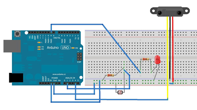
First, let's start with a LDR. Wire up the circuit according to the pic given below.
All done? Let's start with the coding part. Basically what we want to do, is to define an input for the LDR, begin a serial connection(because that's what is used for getting output from the arduino), then print the values to the screen! So we'll do just that now!
int ldrPin = 1;
void setup()
{
Serial.begin(9600); // Specifying the baud rate.
}
void loop ()
{
Serial.println(analogRead(ldrPin)); // telling the serial connection to print the values read from the pin
delay(1000); // delay of 1 second
}
Done! Now upload the code to the board and start the serial monitor. You'll now see some values coming in from the arduino. Now put your hand over the LDR and the values reduce. You've just built your ambient light sensor! To get more resolution in the values just lower the value of the resistor. You can add an opamp too, but that is more complicated and I wouldn't dwell on it now.
So we will now create a simple code to turn on an LED the moment, the value of the LDR drops below a certain level. Connect the LED to the arduino as you would normally without letting the presence of LDR affect it. A resistor should be connected in series to the arduino. Let's add the code now. Since we are not using the serial communication, I have not included the code for that.
int ldrPin = 1;
int ledPin = 9;
void setup()
{
pinMode(ledPin, OUTPUT);
}
void loop ()
{
int val = analogRead(ldrPin);
if (val < 850 ) digitalWrite(ledPin, High); // the moment ambient light level falls below 850, our LED will be
// turned on
else digitalWrite(ledPin, LOW);
}
Test it out. But if you think this is nice, then surely you'll find the next one better. In this project, we use the map function to control the brightness of the LED as a function of amount of light reaching the LDR. We only need to make a few changes to the last program.
int ledPin = 9;
void setup()
{
pinMode(ledPin, OUTPUT);
}
void loop ()
{
int val = analogRead(ldrPin);
val = constrain(val, 700, 900);
int ledLevel = map(val, 700, 900, 255, 0) ;
analogWrite(ledPin, ledLevel);
}
Great! Notice that I have added two new functions. The first one is for the constraint of values from the LDR. What it does is that it sets the values below 700 to 700 and values greater than 900 to 900. I'll tell you why I did that. The next function is the map function. Basically it just takes the inputs in and gives the output according to the limits set by you. In the above case the limits of the input are 700 and 900. So the function will give output between 255 and 0. Since we need an inverse relation( the led should glow when light is low!) we specify 255 first, rather than 0. But what happens if the input value is less than 700? Well, that is exactly what the constrain function is used for. To prevent the arduino from returning garbage values, we have constrained the input.
Congrats !! You just made a nightlight! No longer do you have to be afraid of monsters under your bed or in your closet! Naturally, you can use other inputs like thermistors, range finders to give analog values.
So you think this was good?! No just wait till you see the next one!
To wrap up the post, I will make an emergency light system using an LDR and an IR range sensor as inputs. In this case, the LED turn on only if movement is detected. Just hook up the LDR like in the first project and then the IR module. The IR module has three wires, the signal(yellow), power(red) and ground(black). Plug the red wire in the +5V jack, black in GND, and yellow in any analog pin, say 4.
Let's see the code now.
int irPin = 4;
int ldrPin = 1;
int ledPin = 9;
// Create Variables to keep track of distance
int prevDist = 0;
int currentDist = 0;
//Set the threshold for movment
int thresh = 100;
void setup()
{
pinMode (ledPin, OUTPUT);
}
void loop()
{
int ldrval = analogRead(ldrPin);
int currentDist = analogRead(irPin);
//Check for movement
if (currentDist == prevDist + thresh || currentDist == prevDist - thresh && ldrval < 850)
{
digitalWrite(ledPin, HIGH);
delay(10000);
}
else
{
digitalWrite(ledPin, LOW);
}
// Set the values to original
prevDist=0;
currentDist=0;
}
Thanks for reading my tutorial! Hope I left you brainier than before! I think I will do something on motors in my next post! Keep reading!
Godspeed! Cheers!


0 comments:
Post a Comment
Do Comment on Anything you like or dont like!