Showing posts with label Arduino. Show all posts

Monday, October 29, 2012

0 Arduino Robot 1 - The InsectBot

Hi, guys! I hope you liked my earlier post on making a distance display. So here I am again, and this time I'm going to show you, how to build a robot! Though it's not much of a robot, but I'm sure it'll be fun to watch! Basically the Insect will just squirm it's way around, but if you want, you can actually connect a distance sensor to the arduino and use it for object detection and avoidance!
So let's get started! 

You're gonna need :

  • Arduino Board
  • 2 Servo Motors (I prefer micro servos)
  • Stiff wire ( I used an old hanger wire)
  • 9v battery and it's clip
  • Heat Shrink tubing
  • Glue
  • My tutorial on controlling Servos
So first you need to bend the wire to make it look something like the pic below. Basically this is the structure of the legs.

Then you need to glue the wires to the attachment for the Servo. And it should look something like this.

After that, you need to attach the servos together to make it look like this. These will be the main body of the Insect.

Put in the code for centering the Servos. Then attach the legs to them. You've just created the body for your very first robot! Now attach the servos to the Arduino Board as I showed in  my tutorial, and then program the Insect for the walk. The Code is given below:

//For Centering the servo


Servo fServo;
Servo rServo; 
void setup()
{
fServo.attach(8);
rServo.attach(9); 
fServo.write(90); 
rServo.write(90);
}
void loop()
{
delay(500);
}

//For the Walk


#include <Servo.h>
Servo fServo;
Servo rServo;
int center = 90; 
int frUp = 72; 
int flUp = 108; 
int brForward = 75; 
int blForward = 105;
void moveForward()
{
frontServo.write(frontRightUp);


rServo.write(blForward);
delay(125);
fServo.write(center);
rServo.write(center);
delay(65);
fServo.write(flUp);
rServo.write(brForward);
delay(125);
fServo.write(center);
rServo.write(center);
delay(65);
}
void setup()
{
fServo.attach(8);
rServo.attach(9);
}
void loop()
{
moveForward(); 
delay(150); //time between each step taken, speed of walk
}

Now all you have to do is just plug out the Arduino from the USB, plug in a battery and make the Board a rider on the insect!
Although this was just like a 'Hello World' Project for Robotics, I'll be posting many more progressively projects on Robotics! So don't forget to check in every now and then!
Cheers!




Friday, September 28, 2012

0 Arduino Project 7 - Connect an LCD module to an Arduino and Make a distance display.

You are starting to build confidence in your arduinoing capabilities now aren't you? Gives you satisfaction to know that you are really progressing in something doesn't it? Right! So that's why I'm here with a new tutorial which will show you how to interface an LCD with your arduino. Although it involves some amount of soldering and wiring, it's still a fairly easy concept to grasp. Once you get the theory behind how an LCD module is connected, you will have no difficulty in remembering how to connect it the next time you want to use it. So let's get started shall we?
In this tutorial, we will use a 16X2 LCD having HD44780 driver. You can identify them by their 16 pin connectors.
Okay so first off, I'm going to list out the function of each pin of the LCD module.
Each LCD has 16 pins of which we will be using 12 today.

VCC - Ground Voltage
VDD - +5V
RS    - Register Select controls where in the LCD's memory the data is being written.
R/W  - Read/Write, enables reading or writing mode
E       - Enables writing to the registors
D0-8 - Data Transfer buses
Vo    - Controls the Contrast
A and K control the LED backlight.

Wiring the LCD to the Arduino Via a Breadboard

Wire up the circuit according to the figure given below (courtesy : www.arduino.cc ).

Software for Reading and Writing Data from and to the LCD

The following code will allow you to enable the serial function of the arduino to communicate with it and consequently to give instructions to it to control the LCD module.

#include <LiquidCrystal.h>
// LiquidCrystal display with:
// rs on pin 12
// rw on pin 11
// enable on pin 10
// d4-7 on pins 5-2
LiquidCrystal lcd(12, 11, 10, 5, 4, 3, 2);
void setup()
 {
 Serial.begin(9600);
 lcd.begin(16, 2);
 lcd.clear();
 lcd.setCursor(0,0);
 lcd.print("It Works!");
 lcd.setCursor(0,1);
 lcd.print("Rules");
 }
void loop()
 {
   if (Serial.available())
   {
       char ch = Serial.read();
       if (ch == '#')
        {
            lcd.clear();
         }
       else if (ch == '/')
         {
             lcd.setCursor(0,1);
          }
       else
  {
     lcd.write(ch);
   }
 }
}

Now upload the code to the board, open the Serial Monitor from the console and enter some text to try it out!


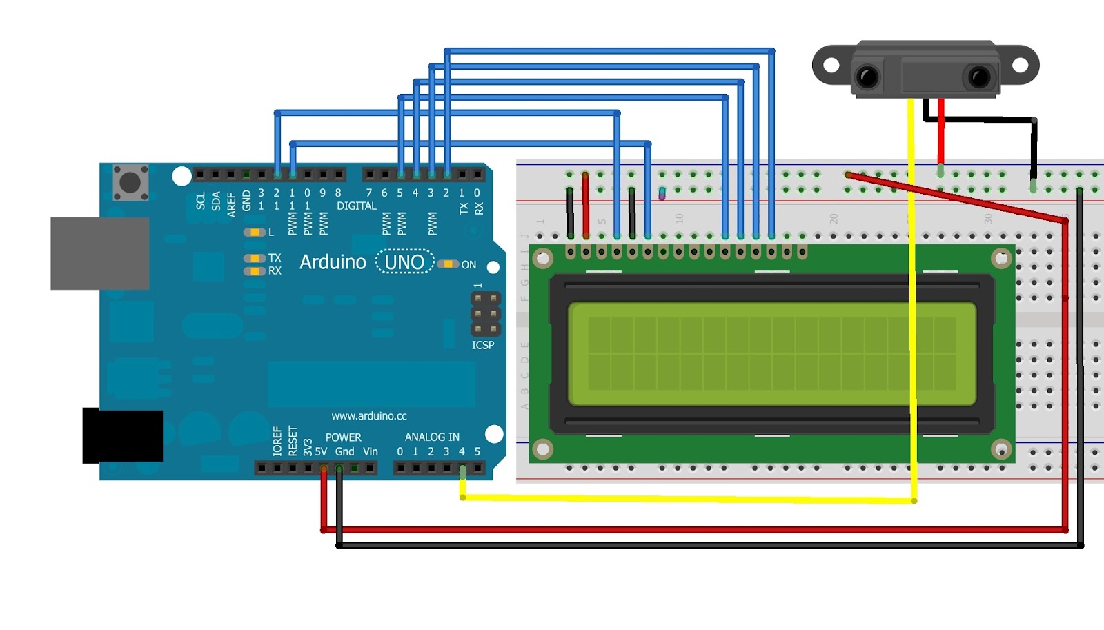
Next I will use an IR ranger sensor to measure the distance of an object and print the values to the LCD. This is a little more complex code and function, so I suggest that before reading this tutorial, you read my tutorial on working with IR sensors.  
Okay, now hook up the LCD module according to the instructions above but add the IR sensor on the analog pin 4 so that the whole circuit looks like this:

Now this is the code for the assembled hardware.

#include <LiquidCrystal.h>
// LiquidCrystal display with:
// rs on pin 12
// rw on pin 11
// enable on pin 10
// d4-7 on pins 5-2
LiquidCrystal lcd(12, 11, 10, 5, 4, 3, 2);
int irPin = 4;
void setup()
 {
 lcd.begin(16, 2);
 lcd.clear();
 pinMode(irPin, INPUT);
 }

void loop()
 {
  float volt = analogRead(irPin)*0.0048828125;   
  float val = 65*pow(volt, -1.10);         
  lcd.print(val);                     
  delay(100);
}

The code in loop is the program is for the displaying the actual distance of the obstacle, rather than the analog values of the Sharp IR sensor. To get an explanation for how it works, you can go to this link. (I'm too lazy to explain the whole process!) or if you do not want to get the distance, only the analog values then you can replace this:

 float volt = analogRead(irPin)*0.0048828125;   
  float val = 65*pow(volt, -1.10);         
  lcd.print(val);                     
  delay(100);

by this:

val = analogRead(irPin);
lcd.print(val);
delay(100);
Like this project, you can build others like a digital thermometer! Or for that matter any project that involves analog values. Don't take any guidance on that, first try it yourself.
Have fun with your new project and needless to say, whenever in doubt just comment on the post, mail me or google it!!

Cheers! :)


Tuesday, September 18, 2012

0 Arduino Project 6 - Inputting Analog Values into Arduino and mapping them to control different functions.

Hi people! So now enough with those simple boring LED projects. From now on I will not be posting any LED tutorials - at least not the simple ones! As is evident from the title, today I'll be showing you how to recieve an analog input from sources like a Light Dependent Resistor(LDR) and an Infrared Sensor.
First, let's start with a LDR. Wire up the circuit according to the pic given below.


All done? Let's start with the coding part. Basically what we want to do, is to define an input for the LDR, begin a serial connection(because that's what is used for getting output from the arduino), then print the values to the screen! So we'll do just that now!

int ldrPin = 1;

void setup()
{
Serial.begin(9600);      // Specifying the baud rate.
}

void loop ()
{
Serial.println(analogRead(ldrPin));  // telling the serial connection to print the values read from the pin
delay(1000);                                   // delay of 1 second
}

Done! Now upload the code to the board and start the serial monitor. You'll now see some values coming in from the arduino. Now put your hand over the LDR and the values reduce. You've just built your ambient light sensor! To get more resolution in the values just lower the value of the resistor. You can add an opamp too, but that is more complicated and I wouldn't dwell on it now.
So we will now create a simple code to turn on an LED the moment, the value of the LDR drops below a certain level. Connect the LED to the arduino as you would normally without letting the presence of LDR affect it. A resistor should be connected in series to the arduino. Let's add the code now. Since we are not using the serial communication, I have not included the code for that.


int ldrPin = 1;
int ledPin = 9;

void setup()
{
pinMode(ledPin, OUTPUT);
}

void loop ()
{
int val = analogRead(ldrPin);     

if (val < 850 ) digitalWrite(ledPin, High);  // the moment ambient light level falls below 850, our LED will be
                                                               // turned on
else digitalWrite(ledPin, LOW);
}

Test it out. But if you think this is nice, then surely you'll find the next one better. In this project, we use the map function to control the brightness of the LED as a function of amount of light reaching the LDR. We only need to make a few changes to the last program.


int ldrPin = 1;
int ledPin = 9;

void setup()
{
pinMode(ledPin, OUTPUT);
}

void loop ()
{
int val = analogRead(ldrPin);
val = constrain(val, 700, 900);                        
int ledLevel = map(val, 700, 900, 255, 0) ;

analogWrite(ledPin, ledLevel);
}

Great! Notice that I have added two new functions. The first one is for the constraint of values from the LDR. What it does is that it sets the values below 700 to 700 and values greater than 900 to 900. I'll tell you why I did that. The next function is the map function. Basically it just takes the inputs in and gives the output according to the limits set by you. In the above case the limits of the input are 700 and 900. So the function will give output between 255 and 0. Since we need an inverse relation( the led should glow when light is low!) we specify 255 first, rather than 0. But what happens if the input value is less than 700? Well, that is exactly what the constrain function is used for. To prevent the arduino from returning garbage values, we have constrained the input.
Congrats !! You just made a nightlight! No longer do you have to be afraid of monsters under your bed or in your closet! Naturally, you can use other inputs like thermistors, range finders to give analog values.
So you think this was good?! No just wait till you see the next one!
To wrap up the post, I will make an emergency light system using an LDR and an IR range sensor as inputs. In this case, the LED turn on only if movement is detected. Just hook up the LDR like in the first project and then the IR module. The IR module has three wires, the signal(yellow), power(red) and ground(black). Plug the red wire in the +5V jack, black in GND, and yellow in any analog pin, say 4.
Let's see the code now.


// Define the pins
int irPin = 4;
int ldrPin = 1;
int ledPin = 9;

// Create Variables to keep track of distance
int prevDist = 0;
int currentDist = 0;

//Set the threshold for movment
int thresh = 100;

void setup()
{
pinMode (ledPin, OUTPUT);
}

void loop()
{
int ldrval = analogRead(ldrPin);
int currentDist = analogRead(irPin);

//Check for movement
if (currentDist == prevDist + thresh || currentDist == prevDist - thresh && ldrval < 850)
{
digitalWrite(ledPin, HIGH);
delay(10000);
}
else
{
digitalWrite(ledPin, LOW);
}
// Set the values to original
prevDist=0;
currentDist=0;
}

Thanks for reading my tutorial! Hope I left you brainier than before! I think I will do something on motors in my next post! Keep reading!
Godspeed! Cheers!

Tuesday, August 28, 2012

0 Arduino Project 5 - Controlling a DC motor and a Servo Motor

Okay, so now I've shown you enough projects on LED's and it's time to move on! This project will show you how to control a DC motor and servo motor with an arduino. This is just a basic projetct in which you will learn how to rotate a servo back and forth, and to any position you want, speed up a DC motor and speed it down. So let's get it started!
Things you will need:

  • An Arduino Board
  • A DC motor
  • A servo motor
  • A breadboard
  • Some jumper wires
  • A transistor (NPN)
  • A diode
  • A capacitor (1 microFarad)
First up is controlling a DC motor - 
The schematic is shown here:

Now what the transistor does is, that it prevents the current from going into the motor if it's below a certain level. This means that we can control the speed of the motor by varying the amount of current that goes into the transistor (which of course is controlled via Arduino). The combination of the capacitor and the diode acts as a filter to prevent electrical noise. Now that you have the schematic, go ahead and wire up the circuit.

Now for the programming part, I will first give you the code with the explanation in the comments.

int MotorPin =9; // Tells the Arduino that motor is connected to pin 9

void setup()
{
pinMode (motorPin, OUTPUT); // Sets the motor as output
}

void loop()
{
for (int i=0; i<=255; i++)    // Creates a variable that starts the arduino at 0 speed and increments till 255
{
analogWrite(motorPin, i);   // Actually executes the previous line
delay(10);                         // Gives a delay of 10ms in each increment
}
delay(1000)                      // Holds it at top speed for a second
for (int i=255; i>=0; i--)    // Brings the motor back from top speed to stationary
{
analogWrite(motorPin, i);  // Executes previous
delay(10);
}
delay (1000)                   // Holds the motor at zero speed for a second
}

Note that the values only go up to 255. Why is that, you might ask? Well the answer is that what we are feeding to the motor, are analog values. Unlike digital values which have 2 states only, analog values can have 256 or even 1024 states. Since the motor is of 8 bit resolution, it can have 2^8= 256 states ( 0 - 255). If you did take the values above 255, the motor will show unpredictable behaviour. This is all for the lesson on DC motors.
You are welcome to come up with your version of the code and post it in the comments!

Now to the Servo motors! So what actually are servo motors? They are just motors with some modifications in them which allows them to turn at precise angles and unlike plain old motors, they can't do full revolutions.

Here to keep, the project simple, I will not use any addons with the servo. just connect the servo to the arduino and write a software that controls it. Though servos require some external power to work efficiently, for the purposes of this project the power supplied by the arduino is sufficient. Or one thing you can do is attach a 5V power source directly to the servo.
 If you notice, there will be three wires connected to the servo. The black is for ground and will go to the pin marked GND in the arduino. The red one is for the power and should go to the pin marked 5V. You can also connect the red and black wire to a 5V power source. DO NOT connect the servo to a source greater than 5V, otherwise you'll fry it! The last yellow one is the data wire that tell the servo what to do. This goes into any digital output pin, I'll use pin 9 for the purposes of this tutorial.
 Now for the coding part. Again I will just write the code and explain it in the comments.


#include <Servo.h>

Servo arushservo;                          // create servo object to control a servo
                                     

int i = 0;                                         // variable to store the servo position

void setup()
{
  arushservo.attach(9);                   // attaches the servo on pin 9 to the servo object
}


void loop()
{
  for(i = 0; i<= 180; i+20)              // goes from 0 degrees to 180 degrees
  {                                                 // in steps of 20 degree
    myservo.write(i);                       // tell servo to go to position in variable 'i'
    delay(1000);                             // waits 1 sec for the servo to reach the position
  }
  for(i = 180; i>=0; i-20)               // goes from 180 degrees to 0 degrees
  {                              
    myservo.write(pos);                  // tell servo to go to position in variable 'i'
    delay(1000);                             // waits 1 sec for the servo to reach the position
  }
}


 I think that should do the trick! Just upload the code to the board and watch the servo turn! It's exciting because you know you have told the servo to turn! There are many ways by which you can use an input to control the output of the servo. Some of which I will post at a later time! So that's all for now folks. See ya in the next post which will probably be about distance measurment!
Oh yeah! and if you've got any doubt whatsoever, just comment or mail me!

Sunday, August 26, 2012

0 Arduino Programming - Lesson 1

Hi folks! Been a long time since my last post but this time imma teach you programming! This is a post about the basics of arduino programming.
Now, the arduino is not a language of its own, but was developed from C. Since C looks like it has been designed by dyslexic aliens, and is very difficult for beginners to pick up, the designers of arduino decided to do some modifications in thier IDE to make the language look like plain english. Believe you me, if you know nothing about arduino, and start to read a program, you will be able to understand what exactly its author intended the hardware to do.
For example, let's review the following lines of code:


/*
Blink
Turns on an LED on for one second, then off for one second, repeatedly.
*/
void setup() {
// initialize the digital pin as an output.
// Pin 13 has an LED connected on most Arduino boards:
pinMode (13, OUTPUT );
}
void loop() {
digitalWrite(13, HIGH);  // set the LED on
delay(1000);     // wait for a second
digitalWrite(13, LOW);  // set the LED off
delay(1000);     // wait for a second
}


  • A slash followed by an asterisk (/*) opens a block where you can input your comments (they are ended by a */). Two forward slashes (//) indicate that the rest of the line is a comment. Note that comments are not a part of the compiling process, they are there only for the ease of humans to read the piece of code.
  • The setup() function executes in the beginning of a program, and it's a one-time declaration. The setup() function will be called automatically immediately after the Arduino is powered or has been programmed. 
  • Calling a function consists of a return value of a function (void), the name of the function (setup), and a list of parameters in parentheses. This function does not take parameters, so there is nothing inside the parentheses. The setup function does not return values, so its type is void (empty). When calling a function, commands are listed within a block of code, which is enclosed in curly braces ({}).
  • This setup() function includes only one command, which sets the pin connected to the LED into output mode. It calls the pinMode() function, which is defined in the Arduino libraries. OUTPUT is a constant defined within Arduino. When using digital pins on an Arduino, you must always declare them to be in either OUTPUT or INPUT mode.
  • As is required by the C language (which Arduino is based on), a line ends with a semicolon.
  • The majority of the execution time of the program will repeat the loop() function. The loop() function is called automatically (and repeatedly) after the setup() function finishes.
  • To address a digital pin that has been set to be an OUTPUT, we use the digitalWrite() function. Set digital pin 13 on HIGH (which means +5V). Digital pin 13 is unique in that Arduino has a built-in LED and resistor attached to it, specifically for debugging purposes. The LED will light up. The pin remains on HIGH until we address the pin with another call from digitalWrite().
  • Wait 1,000 milliseconds (1,000 one-thousandths of a second, totaling one full second). The LED is lit all the time.
  • Switch the pin off (LOW) and wait again for a second. This is the last command in the loop() function, which means that the execution of the loop() function ends.
See how simple that was! As you practice with arduino, you will begin to develop your own interpretation of  the language, which will allow you make the codes shorter and shorter.
In the next lesson, I will show you how to attach various peripherals to your arduino, and control them via software. 
That's me signing off for today! See ya in the next post!


0 Arduino Project 4 - Making A Keypad Security Lock

You, the evil genius wouldn't rest easy till you are sure that all of your creations are locked away somewhere safe, now would you? Well, this project is exactly about that! I'm gonna show you how to make your very own keypad security lock using an arduino board and a bit of cunning. 

 Parts Needed

  • Arduino Uno or a clone
  • Two 270 Ohm metal film resistors
  • A Green 5mm LED
  • A Red 5mm LED
  • A 4X3 Matrix Keypad

Understanding the Concept

The key switches are placed at the intersection of row and column wires. When a key is pressed, it connects a specific row to a specific column. By arranging the keys in a grid like this, it means that we only need to use 7 (4 rows + 3 columns) of our digital pins rather than 12 (one for each key). However, it also means that we have to do a bit more work in the software to determine which keys are pressed. The basic approach we have to take is to connect each row to a digital output and each column to a digital input. We then put each output high in turn and see which inputs are high.

The Adjacent figure shows how you can connect 7 pins to the keypad. Now, we just need to find out which pin on the keypad corresponds to which row or column. If you are lucky, the keypad will come with a datasheet that will tell us this. If not, get some paper, draw a diagram of the keyboard connections, and label each pin with a letter from a to g. Set the multimeter to continuity so that it beeps when you connect the leads together.  Then write a list of all the keys. After that, hold each key down in turn, and find the pair of pins that make the multimeter beep indicating a connection. If you are confused, each pin will have two keys that make the multimeter beep. Release the key to check that you have indeed found the correct pair. After a while you will be able to see how the pins relate to rows and columns. Note that conveniently the keypad  has seven pins that will just fit directly into the Digital Pin 1 to 7 socket on the Arduino board, so we only need the breadboard for the two LEDs.

Software

You may think that we would just write a software which interprets which key is pressed by receiving signals from the pins and the game would be over, but this is not the case. The key doesn't simply go from being open to being closed when you press it, but opens or closes many times. This is called bouncing and we need to incorporate some mechanism which overcomes bouncing. The mechanism will be called debouncer.
No no, you need to fret! Because fortunately for us, there exists a library that handles this for us. This is the link to the library. To install it, just extract from the zip folder, and paste the extracted folder in C:\Program Files\Arduino\Arduino-0017\hardware\libraries or where ever you have installed the arduino IDE. Check that the library is installed by restarting the IDE, starting a new sketch, and choosing the menu option Sketch 
Import Library | Keypad. This will insert the text “#include <Keypad.h>” on the top of the file. The code that I'm going to show you is just an example. You may have to change your int pins to agree with the layout of your keypad.

Here's the code:

#include <Keypad.h>
char* secretCode = "1234";
int position = 0;
const byte rows = 4;
const byte cols = 3;
char keys[rows][cols] = {
{'1','2','3'},
{'4','5','6'},
{'7','8','9'},
{'*','0','#'}
};
byte rowPins[rows] = {2, 7, 6, 4};
byte colPins[cols] = {3, 1, 5};
Keypad keypad = Keypad(makeKeymap(keys), rowPins, colPins, rows, cols);
int redPin = 9;
int greenPin = 8;
void setup()
{
pinMode(redPin, OUTPUT);
pinMode(greenPin, OUTPUT);
setLocked(true);
}
void loop()
{
char key = keypad.getKey();
if (key == '*' || key == '#')
{
position = 0;
setLocked(true);
}
if (key == secretCode[position])
{
position ++;
}
if (position == 4)
{
setLocked(false);
}
delay(500);
}
void setLocked(int locked)
{
if (locked)
{
digitalWrite(redPin, HIGH);
digitalWrite(greenPin, LOW);
}
else
{
digitalWrite(redPin, LOW);
digitalWrite(greenPin, HIGH);
}
}


The loop function checks for a key press. If the key pressed is # or *, it sets the position variable to 0. If, on the other hand, the key pressed is one of the numerals, it checks to see if it is the next key expected (secretCode[position]) is the key just pressed, and if it is, it increments position by one. Finally, the loop checks to see if position is 4, and if it is, it sets the LEDs to their unlocked state. Then it waits a second, and turns the red light green. Load the completed sketch for Project 10 from your Arduino Sketchbook and download it to the board.
If you have trouble getting this to work, it is most likely a problem with the pin layout on your keypad. So persevere with the multimeter to map out the pin connections.
And it goes without saying that if you have any problems, any at all, just mail me or comment.
OVER AND OUT.

Friday, June 15, 2012

0 Arduino Project 3 - Morse Code Translator

This project uses the same apparatus as the projects 1 and 2, but has an upgraded sketch that allows us to write a sentence on the computer and the arduino translates that for us in long blinks and short blink. (Morse Code)

Hardware, Materials and Construction

Refer to the Project 1

Software

For this project to work, we first have to understand the concept of loops and arrays.

Loops:
As in project 2, when we had to flash the LED 3 times, we had no problem in repeating the command. But what if we want the LED to flash say 100 times? In that case we use loop function. An example is given below

for (int i = 0; i < 100; i ++)
{
flash(200);
}

The 'for' loop is a function that takes three arguments to perform the work given to it. As long as the conditions are satisfied, the function is valid. After that the function is void and Arduino follows the command after that. The first command 'int i = 0' sets the initial value of the variable to 0. The second command sets the condition that as long as the value of variable is less than 100, the function is valid. The third command says that after each blink, the value of variable increases by 1. So the LED will blink a 100 times. The code on curly braces tells the arduino what to do (in this case flash).
Note - To use this code by itself, you have to define the function 'flash' first.

Arrays:
Arrays are used to contain any number of values. Loops only contain one value usually 'int'. You can access the variables by its position in an array. Now let's see an array of durations.

int durations[] = {200, 200, 200, 500,
500, 500, 200, 200, 200}

The ' [] ' indicates that the function is an array. As in the previous array, if you set the variables, you need not specify any quantity in the square brackets. But if you have not specified the variables, you have to specify the number of variables used. As in 

int durations[10];

This is the modified loop method which uses an array.

void loop()
// run over and over again
{
for (int i = 0; i < 9; i++)
{
flash(durations[i]);
}
delay(1000);
// wait 1 second before we start
// again
}

Having said that, let's have a look at the actual code for the morse translator.

int ledPin = 12;
char* letters[] = {
".-", "-...", "-.-.", "-..", ".", "..-.", "--.", "....", "..", // A-I
".---", "-.-", ".-..", "--", "-.", "---", ".--.", "--.-", ".-.", // J-R
"...", "-", "..-", "...-", ".--", "-..-", "-.--", "--.." // S-Z
};
char* numbers[] = {"-----", ".----", "..---", "...--", "....-", ".....", "-....",
"--...", "---..", "----."};
int dotDelay = 200;
void setup()
{
pinMode(ledPin, OUTPUT);
Serial.begin(9600);
}
void loop()
{
char ch;
if (Serial.available()) // is there anything to be read from USB?

{
ch = Serial.read(); // read a single letter
if (ch >= 'a' && ch <= 'z')
{
flashSequence(letters[ch - 'a']);
}
else if (ch >= 'A' && ch <= 'Z')
{
flashSequence(letters[ch - 'A']);
}
else if (ch >= '0' && ch <= '9')
{
flashSequence(numbers[ch - '0']);
}
else if (ch == ' ')
{
delay(dotDelay * 4); // gap between words
}
}
}
void flashSequence(char* sequence)
{
int i = 0;
while (sequence[i] != NULL)
{
flashDotOrDash(sequence[i]);
i++;
}
delay(dotDelay * 3); // gap between letters
}
void flashDotOrDash(char dotOrDash)
{
digitalWrite(ledPin, HIGH);
if (dotOrDash == '.')
{
delay(dotDelay);
}
else // must be a -
{
delay(dotDelay * 3);
}
digitalWrite(ledPin, LOW);
delay(dotDelay); // gap between flashes


Paste the above sketch in the Arduino environment and load it to the arduino board. To use the Morse code translator, we need to use a part of the arduino environment called the serial monitor. To access it, click the rightmost icon on the top bar. A popup will open. The serial monitor is used to send commands to the arduino and see it's reply. It is here that you will write your sentences and see your arduino translate it into morse code. Enjoy !! Bewilder the nieghbours with your gadget! 
Au revoir jusqu'à ce que le prochain post!

Monday, June 11, 2012

0 Arduino Project 2 - Morse S.O.S. Code Flasher


So to start this project, you should have the Arduino interfaced with your operating system. If not, you can read the tutorial here. We will use the Arduino project 1 as a base for this project. So if you didn't already do that project, it is absolutely necessary that you do it now. Just for the knowledge S.O.S in Morse code is            '...---...' So Morse code flashing will consist of three short blinks, followed by three long blinks, followed by three short ones again.

Equipment Required

Same as project 1
  • Arduino Board
  • 5-mm Red LED
  • 270 ohm metal film resistor
The arrangement remains the same too.

Software

Here is the link to the Project 1's code file that you can upload to the board and have your base ready. After this we're gonna make some modifications to the code so that your arduino does not only blink but blink S.O.S. The first step is to modify only the loop function so that it appears as shown here:

void loop()
{
digitalWrite(ledPin, HIGH);      // first dot start
delay(200);
digitalWrite(ledPin, LOW);
delay(200);
digitalWrite(ledPin, HIGH);     // second dot start
delay(200);
digitalWrite(ledPin, LOW);
delay(200);
digitalWrite(ledPin, HIGH);     // third dot start
delay(200);
digitalWrite(ledPin, LOW);
delay(500);
digitalWrite(ledPin, HIGH);     // first dash start
delay(500);
digitalWrite(ledPin, LOW);
delay(500);
digitalWrite(ledPin, HIGH);     // second dash start
delay(500);
digitalWrite(ledPin, LOW);
delay(500);
digitalWrite(ledPin, HIGH);     // third dash start
delay(500);
digitalWrite(ledPin, LOW);
delay(500);
digitalWrite(ledPin, HIGH);     // first dot
delay(200);
digitalWrite(ledPin, LOW);
delay(200);
digitalWrite(ledPin, HIGH);     // second dot
delay(200);
digitalWrite(ledPin, LOW);
delay(200);
digitalWrite(ledPin, HIGH);
// third dot
delay(200);
digitalWrite(ledPin, LOW);
delay(1000);                            // wait 1 second before we start again
}

A copy paste will be highly recommended here! This would work just fine but isn't it too long? We will now try to shorten the code a little bit. We can do that by replacing four lines of code with only a one line function, the function of which we will describe in another line of code.(Don't worry you'll get it when I explain the code). After the above given loop's final curly bracket, add the following function(this was the function that I was talking about):

void flash(int duration)
{
digitalWrite(ledPin, HIGH);
delay(duration);
digitalWrite(ledPin, LOW);
delay(duration);
}

Then replace the loop function with this:

void loop()
{
flash(200); flash(200); flash(200);             
delay(300);                                                 // otherwise the flashes run together
flash(500); flash(500); flash(500);            
flash(200); flash(200); flash(200);           
delay(1000);                                             // wait 1 second before we start again
}
I strongly recommend that you do all of these steps carefully and fully before you read on.
Now I will explain the logic behind this. In the first sketch of this post, we instructed the arduino brain ( how do I explain this?) like we would explain to a 5 year old, explicitly detailing all the work that has to be done. 

But that would be a very tedious task wouldn't it? So we made the board old enough to remember some things in his memory. This is why we created a function after the loop (the second code) . By doing this we made the 12 year old board remember a piece of information. Having done that, we gave a set of instructions (the third code) to the boy for which he would have to refer to the piece of information we gave him earlier and told him how to use it. In this case our work is greatly reduced.
Notice that the name of the function (the second piece) we created is flash. In the third piece of code we just typed out the name 'flash' and the duration for which we want it running in brackets and the Arduino brain immediately referred to the function for help and finished the work!
Here I have uploaded the full sketch for the Morse flasher, but use it only if you didn't get it before. Identify your mistakes and then use it.
With this said folks, I end my post. Will keep on updating the blog with more projects and the next one will have nothing to do with LED's (except a little bit). The next project will be something related to privacy and its gonna be legen...........wait for it..................just comin..............dary!

Saturday, June 2, 2012

0 Arduino Demystified

So, what is Arduino? 

Arduino is an open source elctronics prototyping platform based on easy to learn software and hardware. It can interact with the environment through the plethora of sensors, and can react to the stimulus by the actuators attached to it - all with only your input. Much like teaching a child, you can write programs (The language is one of the easiest to learn), thus instructing if what to do when a certain stimuli is recieved or whether to do anything at all. Due to the inexpensive hardware, open source software, easy to use interface and loads of support on the internet, it has become the most popular prototyping platform in the world!

Getting Started

For beginners, if you are actually (with all your heart) interested in robotics, I would suggest you buy the Arduino Uno. It's inexpensive (you wont regret it even if you burn it!), lots of support available and plenty of connectors.

To begin using Arduino, first go to the Arduino site (www.arduino.cc) and download the software for Mac, PC, or LINUX. You can then either buy an official Arduino, or buy a clone or build your own Arduino board ( the directions for which I will post shortly ), each option less expensive than previous. There are many different types of boards, each with it's own functions. However the programs work with every one of the boards.When you are making a project with an Arduino, you will need to download programs onto the board using a USB lead between your computer and the Arduino. This is one of the most convenient things about using an Arduino. Many microcontroller boards use separate programming hardware to get programs into the microcontroller. With Arduino, it’s all contained on the board itself. This also has the advantage that you can use the USB connection to pass data back and forth between an Arduino board and your computer. For instance, you could connect a temperature sensor to the Arduino and have it repeatedly tell your computer the temperature. The power supply is generally 7-12V so a 9V battery will do just fine for portable applications. What's more? Well you can buy ( or design your own ) so called shields that are just some hardware addons to Arduino for increasing it's functionality and usability. Some of the functions that the shields are used for are :
  • Connection to Ethernet Networks
  • LCD displays and touch screens
  • Wireless data communications
  • Sound 
  • Motor control
  • GPS functionality
  • Many more
You can use prototyping shields to design your own shields.
Without further ado, we will connect the Arduino board to the computer through an A to B USB lead, which is the same lead you use to connect the printer to the computer. If every thing is working okay, the LED on pin 13 will blink once every 2 seconds.

Installation On Windows

Follow the download link on the Arduino home page (www.arduino.cc) and select the download for Windows. This will start the download of the Zip archive containing the Arduino software. The Arduino software does not distinguish between different versions of Windows. The download should work for all versions, from Windows XP onwards. Select the Save option from the dialog, and save the Zip file onto your desktop. The folder contained in the Zip file will become your main Arduino directory, so now unzip it into which ever folder you want, in my case C:\Program Files\Arduino. You can do this rightclicking the Zip file to show the menu and selecting the Extract All option. This will open the Extraction Wizard. This will create a new directory for this version of Arduino in the folder C:\Program Files\Arduino. This allows you to have multiple versions of Arduino installed at the same time, each in its own folder.
Now that we have got the Arduino folder in the right place, we need to install the USB drivers. We let Windows do this for us by plugging in the Arduino board to trigger the Windows Found New Hardware Wizard. Select the option No, Not This Time, and then click Next. On the next screen, click the option
to install from a specified location, enter or browse to the location C:\Program Files\Arduino\arduino-
0017\drivers\FTDI USB Drivers, and then click Next. Note that you will have to change 0017 in the path noted if you download a different version.
The installation will then complete and you are ready to start up the Arduino software itself. To do this, go to My Computer, navigate to C:\Program Files\Arduino\arduino-0017, and click the Arduino icon. The Arduino software will now start. 

Configuring Your Arduino Environment

Whatever type of computer you use, you should now have the Arduino software installed on it. We now need to make a few settings. We need to specify the operating system name for the port that is connected to the USB port for communicating with the Arduino board, and we need to specify the type of Arduino board that we are using. But first, you need to connect your Arduino to your computer using the USB port or you will not be able to select the serial port. The serial port is set from the Tools menu. If you use many USB or Bluetooth devices, you are likely to have quite a few options in this list. On Windows, the serial port can just be set to COM3. From the Tools menu, we can now select the board that we are going to use.

And TADA!, you are ready to use your Arduino board!
You can start modifying your sketches or even creating them by starting with this post

1 How to Make Your Own PCB

Well you might be asking what is the use of making your own PCBs when you get readymade circuits in the market? The obvious answer would be to save a few bucks, but no, there is more. Making PCBs yourself lets you understand the internal workings of the circuit in a way that no teacher or self learner can match. And yes you can save as much as 50% of the cost! You make lots of stuff and attach it to some circuitry, then you won't take out the part till something breaks. You cant go out and keep on buying those expensive premade circuits every time you need one, it's just impractical. So what you do? You make PCBs at home at half the cost, all the while learning the working of that particular circuit and still having fun! And that's exactly what i'm gonna show you today.

Parts List

  • Copper Clad Fibre Glass board (Ask for PCB board). You will usually get this in your local electronics store.
  • An Abrasive Pack
  • Black Laser Printer ( Dont worry if you don't have it, you can print your PCB design on any paper and get it photocopied)
  • Glossy Magazine Paper, or press and peel paper
  • Acetone
  • An Iron Box
  • Etchant like FeCl3 solution or a mixture of Muriatic acid and Hydrogen Peroxide
  • Etchant Container - Any plastic or glass container. Do NOT use a metal container, the etchant will eat through it.
  • Rubber Gloves. You don't want to burn your hands, now do you?
  • Drill. Preferably a drill press, but a hand drill will do, though it will reduce the accuracy (you may end up drilling just out of the designated circle and render the whole PCB useless.
  • Micro Drill bits for drilling the micro holes.
  • Paper Napkins
Now that you have the parts laid out, we dwelve into the actual designing of the circuit. Before the copper board can be etched, we have to have a functioning design. There are many open-source programs that let you design the circuits, but the best I could find and the one I would recommend is the Eagle PCB designer from CADsoft. It can be found at the CADsoft Website and has versions for Windows, Linux, and Mac users. The functionality of the freeware version is only limited by the size it lets you design ( 4 X 3.2 inches )
an enormous number of useful circuits can be built using that size only.

The Procedure 

So now you have got the reference design? Good!
  • Start by printing a design on a glossy paper or a press and peel paper with a laser printer.
  • Put the paper on the board and set the position.
  • Put the centre part of the iron on the paper and hold still, strictly no rubbing.
  • After 5 mins, lift the iron and put another piece of paper between the iron and the paper on the board. Keep the iron on it, hold it from one corner and slowly move the iron all over the board.
  • Let the board cool for 10 minutes and then dip it in warm water, add some soap. Keep it in for 15 mins.
  • Take the board out lightly rub the board (do NOT scratch) to remove the paper completely.
  • You should have the design on the board. If there are any places where the toner did not transfer completely, manually fill them in with a permanent marker pen. But if there are any major defects, then you might have to repeat the whole process again. (You can scratch the toner off and reuse the copper clad board.
  • Now take the etchant you have and pour it in a container. ( If you have muriatic acid and hydrogen peroxide mix them in the ratio of 1:2). And be sure to wear your rubber gloves.
  • Dip the copper clad into the etchant and keep agitating it with a glass rod or a plastic use and throw spoon.
  • After 2-3 minutes, take the PCB out and see whether the copper without the toner has gone or not. If  not, then dip the PCB in for some more time.
  • After you are done with the etching, pour the etchant into a large bucket of water and pour the water into the drain. It is very important that you use a large bucket of water. Keep your face away while pouring and pour a thin stream of the etchant, not the whole container at once.
  • Now give your attention to the PCB. Soak a little acetone in the paper towel, and gently rub the PCB to remove the toner.
  • The PCB is now ready!
I will keep posting the schematics for a variety of useful circuits. For a starter take these sch and brd files for making the BJT H-bridge. You can find out the parts list from the schematic view and view the board design from brd file.

Monday, May 28, 2012

0 Arduino Project 1 - Flashing LED's

In this post, i have aasumed that you have successfully installed the Arduino Environment. If not then please refer to this post .
This is the most basic of the sketches in Arduino and even comes bundled with the program but we've got to start somewhere don't we?
In this project we will learn to modify the Blink sketch, we will increase the frequency of the blinking and then install the modified sketch on our Arduino board. Then we advance by using an external resistor and LED instead of the tiny built in LED.
In this example I have used the Arduino Duemilanove

Editing the software

Loading the Original Sketch(which is Arduino term for program)


  • Open the Arduino Program
  • Select File -> Examples -> Digital -> Blink

 Modifing The Sketch

  • Find the code that says 'delay(1000) ;'. This line instructs the microcontroller to delay the blink by 1000 miliseconds or 1 second. We can change the value 1000 to whatever we like, for this post i will keep it to 500. (Dont keep the value as small as 1 ms , it will make the blink imperceptible).
  • Click the upload botton.
  • It will take 5-10 seconds for the sketch to upload
  • You will notice that the LED has started to blink much faster now!
Congratulations! You just uploaded your first sketch to the Duemilanov.
(Doesn't matter which Board you have, the sketches will always be the same)

Hardware

For this part, you will need
  • A 5mm red LED (However any commonly avalable LED will do.)
  • 270 ohm resistor
  • A pair of pliers
Note - LEDs cannot work standalone, they need a current limiting device to work, hence the resistor.

Procedure

  • Connect (just entangle) one end of the resistor (does not matter which one) with the shorter end of the LED (this is very important). If you do not connect it the correct way, it could fry your board, so be careful.
  • Put the free end of the LED into the 12 numbered pin of the Duemilanove, and the free end of the resistor to the GND pin.
We can now modify the sketch to accomodate the external LED
The only change to the sketch will be changing the line

int ledPin = 13;
// LED connected to digital pin 13

to 


int ledPin = 12;
// LED connected to digital pin 12


Thats because we have connected the LED to 12 pin.
Note - Anything written after // is not read by the arduino program. So it doesn't really matter what you write after it.
Here is the full code, just load it into the arduino environment and upload it to the board.
You can see the original code here


That's all for this post folks!
Please let me know if there is anything i should clarify or add in the comments.
Or if you would simply like to give a compliment, you are welcome! :P


The Engineer's Spot! Copyright © 2011 - |- Template created by O Pregador - |- Powered by Blogger Templates